SMART Status/Fault Monitoring Device
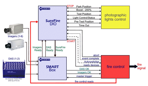
A huge challenge in the crash world is keeping tabs on the status of all your critical data peripherals such as the high-speed imagers and DAS units that collect test data. Most systems have no effective way to distribute the arming and trigger signals to active devices nor to tell the fire (propulsion) control system that some device has a fault and to not continue with the test!
Overview
SMART connects all the pieces so now you can know the status of all your critical data peripherals at a single glance…
Monitors all imagers and DAS units for availability
Distributes the arming signals to all cameras & DAS networks
Distributes the trigger signal to all cameras and DAS networks
Inhibits “start of test” if a fault is detected

Features
n the crash world there are may be separate control systems for the DAS/imagers and fire (propulsion) control. For complete integration, the fire control system normally provides one or two outputs to “ready” the DAS/imager peripherals for the test and one or two input signals that are used to monitor your equipment status by fire control.
SMART takes the fire (or propulsion) control output signals and logically combines them with the signals from the DAS/imager equipment control (EC, i.e.: SureFire™) system. It distributes the combined signals for up to 2 DAS networks and up 8 imager networks. The status of peripherals is logically combined with signals from the EC system and then distributed back to fire control and EC. SMART also distributes the trigger (T0). It takes the T0 signal from the trigger generator and distributes it as a separate signal to each DAS/imager network. SMART also provides an auxiliary trigger input that can be used as a secondary backup trigger signal in case your primary trigger signal is not received or to generate a test trigger.
For safety and reliability, SMART optically isolates all input and output signals and contains fault resistant decision making logic – no single fault in the decision making hardware can result in an incorrect equipment status.
SureFire enables and disables the monitoring of all active instrumentation and display the units' status via the SMART device, according to the configuration of the selected test profile.
For example, SureFire waits for the READY DEVICES signal from sled fire control output and then activates the lights to go to 50% output power to warm-up. After about 2 minutes, SureFire commands the lights to move to the test position and readies the imagers and DAS units. SureFire then commands the lights to go to 200% (boost) output power and sends a SUREFIRE READY signal to the sled fire control input for immediate firing within 10 seconds before the lamps automatically turn off. The sled fire control continues to monitor SUREFIRE READY, and all instrument status’ and aborts if any signal indicates a fault status. SureFire then waits for a MASTER TRIGGER from sled fire control output and then an EVENT COMPLETE. SureFire then commences a download of all data from imagers and DAS.
Optically Isolated Input/Output
Front Panel Indicators (see Front Panel above):
Rear Panel Connections:
Imager Network Connections: 1 to 8 networks
DAS Network Connections: 1 to 2 networks
Master System Connections


